
Translated from the Korean original. Read the original
Selecting an Overspeed Governor and Stand for Heavy Loads
· 4 min read
- Overspeed Governor
- Governor rope
- Switch Tension Device
- Governor Stand
- Rated speed
- Maintenance

Key points
- High-load Overspeed Governors require a combined review of rated speed, load, roping, and interlocking structure.
- The consistency of the drawings, supplied specifications, control panel settings, and actual operating speed must be verified.
- The straightness, entry angle, and tension position of the rope affect the reliability of detection and mechanical transmission.
- The Governor Stand must be checked for flatness, secure mounting, rope path, and inspection accessibility.
- After installation, the overall operating environment must be inspected, including rope sway, uneven wear, and loosened fasteners.
⚠ CautionThis article explains general inspection criteria. For maintenance decisions on a specific installation, please also check that model’s manual and inspection criteria.
Heavy-load elevators have more demanding car load, operating inertia, and machine-room or hoistway layout conditions than standard passenger elevators. In such cases, an Overspeed Governor is not a component that should be selected solely by matching the rated speed. The operating conditions of the main unit, governor rope routing, tension condition, and stand mounting surface must all be checked to reduce the possibility of on-site rework and malfunction.
Rated speed is not only about operating speed
The Overspeed Governor is a critical safety component that detects when an elevator moves at a speed outside the permitted range and is connected so that the Safety Gear can operate. Therefore, the first step in selection is to confirm that the elevator's rated speed falls within the Overspeed Governor's applicable range.
However, at heavy-load sites, judging by the indicated speed alone may be insufficient. The car weight, load capacity, roping method, Traction Machine arrangement, and linkage with the Safety Gear must also be reviewed. Even at the same speed, different load and rope-tension conditions can result in different actual operating environments for the governor rope.
Site engineers must confirm that the rated speed shown on the design drawings matches the rated speed in the actual supplied specifications. At modernisation sites, differences may exist among the original drawings, controller settings, Traction Machine replacement history, and actual operating speed. Such differences can lead to errors in Overspeed Governor selection.
Rope routing is essential for reliable operation
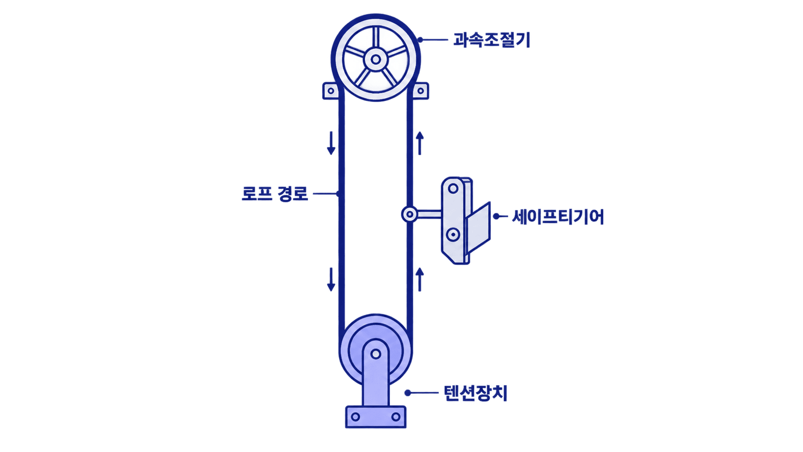
The governor rope forms a path connecting the main unit, Tension Device, and Safety Gear operating mechanism. If this path is unstable, smooth detection and mechanical transmission may be difficult even when the main unit itself is functioning normally.
The first item to check is whether the rope descends stably in a near-vertical line. If the rope interferes with surrounding structures, brackets, piping, or cable trays, friction and uneven wear may occur. Even if no problem is apparent immediately after installation, the area of interference may expand due to operating vibration and long-term use.
The second item is the direction in which the rope passes over the Sheave and the rope entry angle. If the rope does not enter the Overspeed Governor Sheave naturally, it may run toward one flange and wear unevenly, or slight oscillations may increase during operation. Because heavy-load elevators have greater rope tension and inertia, even minor misalignment becomes an inspection point.
The third item is the position of the Tension Device. The Tension Device helps control rope sag and stabilise tension. The development results for D&D's DND-HLGV-001 heavy-load Overspeed Governor include a Switch Tension concept that allows rope sag to be checked in advance. At heavy-load sites, this type of tension-checking mechanism helps make maintenance decisions clearer.
The reference surface matters more than the stand height
An Overspeed Governor Stand is not merely a support on which the main unit rests. It serves as an installation reference that determines the shaft centre of the main unit, the rope drop position, and inspection access. In particular, at sites where the machine-room floor or overhead structure is uneven, the stand conditions must be reviewed during the selection stage.
The stand mounting surface must be sufficiently level and rigid. If the floor level is uneven or the anchors are not securely fixed, operating vibration may be transmitted to the main unit. If the main unit is installed with even a slight tilt, the rope may move away from the centre of the Sheave, potentially causing rope wear and noise over time.
When reviewing stand products such as the DND Overspeed Governor Stand PCD240, the site assessment must consider not only the fastening positions but also whether the main unit and rope routing are properly aligned together. Even if the stand fits, walls, inspection platforms, or beam structures nearby may deflect the rope and require modification or reinstallation.
Adequate space must also be provided for inspectors to gain access. Even after installation, the Overspeed Governor must be checked for the condition of its seals and switches, rope travel, and the presence of foreign material. If the installation area is too confined, the quality of periodic inspections may decline.
Heavy-load sites require a pre-checklist
At heavy-load elevator sites, it is advisable to prepare a simple checklist before selecting the Overspeed Governor. Drawing reviews and on-site measurements should not be treated separately but compared using the same criteria.
| Item to check | On-site assessment criterion |
|---|---|
| Rated speed | Confirm that the design speed matches the actual operating conditions. |
| Load conditions | Check that the car deadweight, load capacity, and roping conditions match the selected specifications. |
| Rope routing | Confirm that a straight, interference-free path is maintained from the main unit to the Tension Device. |
| Stand mounting surface | Check levelness, secure fixing, and interference with surrounding structures together. |
| Inspection access | Review whether the rope, switches, and sealed sections can be inspected after installation. |
This checklist is both a product-selection tool and a means of reducing installation risk. In particular, when replacing components in an existing elevator or working at large freight or special-purpose sites, on-site measurement becomes more important because the drawings and actual structures may differ.
Maintenance inspection points
After installation, inspections should not focus solely on the Overspeed Governor main unit. Rope oscillation, tension condition, uneven wear in the Sheave groove, loosening of the stand fasteners, and interference with surrounding structures must also be checked.
If irregular noise is heard during operation or there are signs that the rope is running to one side, it is advisable not to assume that the issue is simply related to lubrication. A tilted stand, an incorrect rope entry angle, or a change in the Tension Device position may be the cause.
At heavy-load sites, small installation errors can accumulate and alter the operating environment of safety components. Selecting an Overspeed Governor should not be a procedure that ends with confirming the product name. It should be a process of reviewing the rated speed, rope routing, and stand installation conditions as a single system. This approach is a practical starting point for reducing the possibility of malfunction and the risk of reinstallation.
Frequently asked questions
- Can a standard Overspeed Governor be used at a heavy-load site?
- This cannot be determined solely by whether the rated speed matches. The load conditions, roping method, rope routing, and linkage with the Safety Gear must also be reviewed.
- What should be checked first when selecting a stand?
- Along with whether the main unit can be fastened, check that the rope enters the centre of the Sheave naturally. The levelness and secure fixing of the mounting surface are also important.
- Why is rope sag a problem?
- Rope sag may indicate reduced tension or unstable routing. The tension condition must be maintained to ensure stable detection and mechanical transmission.
- What additional points should be checked at modernisation sites?
- Confirm that the existing drawings match the actual site structure. Beams, piping, cables, and inspection platforms may interfere with the rope routing.
Parts covered in this article
Products mentioned above, matched against our catalog.
Need to check whether it fits your site?
Tell us the model and site conditions — our team will confirm the specification and send a quote together with certificates and test reports.


